
In the first part of our article, we introduced the essential concepts of cross-connection control and backflow prevention, providing Public Health Officers with a beginner-friendly guide to these critical topics. If you haven’t read it yet, we highly recommend starting there to familiarize yourself with the key terminology and concepts.
Now, in the second part, we focus on the specifics of mechanical backflow preventers. Using real-life examples from cruise ships, we illustrate their application to guide you in selecting the appropriate devices for various connections.
Ensuring the health and safety of everyone on board doesn’t happen by accident; understanding these devices is crucial for maintaining a potable water supply that is safe for human consumption.
Table of Contents
Backflow Preventer vs Check Valve: What’s the Difference?
Before diving into the various options available in our backflow toolbox, it’s crucial to understand the difference between a backflow preventer and a check valve. This distinction is important for ensuring compliance with the Vessel Sanitation Program’s (VSP) cross-connection control standards.
The Role of Backflow Preventers & Check Valves
Both backflow preventers and check valves are essential components in a plumbing system, designed to maintain the integrity of the water flow. Their primary function is to allow fluids or gases to move in one direction only, thereby preventing reverse flow. However, despite their similar goals, these devices serve different purposes.
What is a Backflow Preventer?
A backflow preventer is a specialized valve designed to stop the reverse flow of water—or a mixture of water and other non-potable substances—within a piping system. Its sole purpose is to prevent contaminated or polluted water from entering the vessel’s drinking water supply. Mechanical backflow prevention devices (BFPs) typically feature multiple check valves and other components to provide robust protection against backflow.
For example, a Dual Check Valve Assembly (with an atmospheric vent) is a type of backflow preventer that includes two check valves and an intermediate atmospheric vent. The vent creates an air gap to prevent backflow due to backpressure or backsiphonage. The two check valves act as primary and backup mechanisms; if one fails, the other ensures continued protection. This combination offers a failsafe design to safeguard the potable water supply. Other types of backflow preventers also incorporate multiple redundant features to enhance protection.
What is a Check Valve?
Check valves, on the other hand, are more general-purpose valves that allow fluid to flow in only one direction. They help prevent backflow, reduce pressure losses, and ensure optimal system performance. Check valves operate using a swinging disc or a spring-loaded mechanism that opens to permit forward flow and closes to block reverse flow.
However, check valves do not provide the same level of protection as backflow preventers and are not suitable for safeguarding drinking water supplies. If debris gets into the check valve, it can cause it to remain open. Without a backup mechanism, this type of malfunction will render the check valve ineffective in a backflow event. Unlike backflow preventers, check valves are used in a variety of applications—not just in potable water systems—including condensate pumps, heat exchangers, wastewater systems, and air compressors.
Why the Distinction Matters
While the definitions of these devices might seem like a matter of semantics, they are not. Backflow preventers are specifically designed to prevent backflow and contamination of the potable water supply, offering a higher level of protection compared to simple check valves. They also tend to have a longer operational lifespan.
Despite this, check valves are still commonly used to prevent backflow in a vessel’s plumbing system, such as preventing the backflow of cold water into the hot water supply and vice versa. This is where the VSP’s definition of a backflow prevention device becomes relevant:
Backflow prevention device: An APPROVED backflow prevention plumbing device that must be used on POTABLE WATER distribution lines where there is a direct connection or a potential CROSS-CONNECTION between the POTABLE WATER distribution system and other liquids, mixtures, or substances from any source other than the POTABLE WATER supply.
VSP 2018 Operations Manual
Understanding these differences ensures that the right devices are used to protect the potable water system, maintaining both safety and compliance with public health regulations.
Note: While mixing hot and cold water doesn’t directly contaminate the main supply, it can create conditions within plumbing components that encourage the growth of Legionella spp. and other opportunistic waterborne bacteria—but that’s a topic for another discussion.
Why Certain Backflow Preventers Are Not Approved by VSP
Double Check Valve Assemblies, which serve as a middle ground between a check valve and a backflow preventer, are not approved for use on cross-connections by the VSP because they lack an atmospheric vent. Only vented backflow preventers meet the VSP’s stringent requirements.
Vented backflow preventers permit air to enter the system, breaking any siphon that might form and effectively preventing backsiphonage. The atmospheric vent is the key component that manages this process. It functions by opening to the atmosphere when there is a drop in supply pressure, which permits air to enter the system and break the vacuum. This mechanism prevents contaminated water from being siphoned back into the potable water supply.
This additional layer of protection makes vented backflow preventers more reliable in preventing contamination compared to their non-vented counterparts. Non-vented backflow prevention devices rely solely on check valves. If a check valve in a vented BFP fails, the venting mechanism still provides a safeguard against backflow, ensuring continued protection. This redundancy is crucial for maintaining the integrity of the potable water supply on a cruise ship.
Types of Backflow Prevention Devices
Mechanical backflow preventers can be broadly categorized into two groups: testable and non-testable.
Non-Testable Backflow Prevention Devices
Non-testable BFPs are more affordable and simpler in design, but their functionality cannot be verified as accurately as testable devices.
VSP standards require annual visual inspections of these devices to check for signs of wear, damage, or leaks. Changes in water quality, such as discoloration, may also indicate a problem with your backflow preventer. Proper installation according to the manufacturer’s instructions is crucial to prevent malfunctions. Typically, these devices should be replaced every 5 to 10 years, depending on usage conditions and manufacturer recommendations. If any signs of degradation are detected, it’s best to replace them promptly to ensure the safety of the vessel’s potable water supply.
Common types found on board include:
Atmospheric Vacuum Breaker
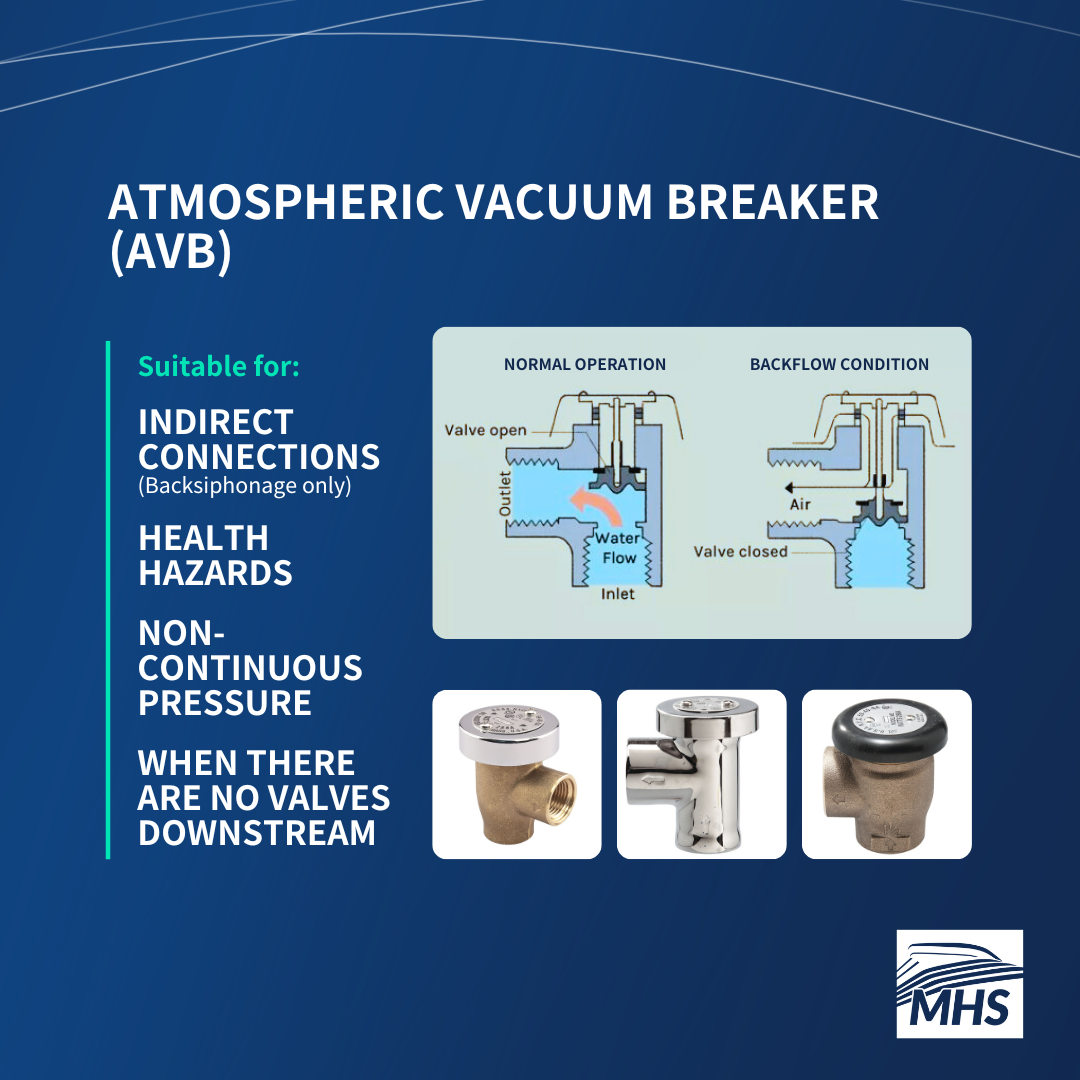
When it comes to ensuring the safety of potable water on a cruise ship, Atmospheric Vacuum Breakers (AVBs) play a crucial role. These devices are among the most cost-effective and straightforward backflow preventers available. Their simplicity allows for easy installation (most of the time), making them a popular choice for various applications on board, such as laboratory equipment or humidifier systems, provided they are not under continuous pressure.
However, the primary use of AVBs on a cruise ship is for toilets. VSP standards mandate that AVBs be installed on the potable water supply for all vacuum toilet systems—consider the number of toilets on board your ship. Specifically, they should be placed on the discharge side of the last valve that controls the water flow when the toilet is flushed.
AVBs are designed to protect against hazards at the point of use and for indirect connections only. In other words, they provide protection against backsiphonage but not backpressure. Despite this limitation, AVBs are considered high-risk protection devices, suitable for applications where health hazards are a concern. Essentially, any backflow preventer that offers health hazard protection is also acceptable for non-health hazard applications.
How Does an AVB Work?
An AVB consists of three main components: a check valve, an air inlet valve, and a vent float. Here’s how each part functions:
- Check Valve: This valve controls the direction of water flow. Under normal conditions, it remains open to allow water to pass through. If the water pressure drops, the check valve closes to prevent backflow.
- Air Inlet Valve: Acting as a safety mechanism, the air inlet valve opens when the check valve closes, allowing air to enter the system. This prevents the formation of a vacuum—hence the name “vacuum breaker”—which could otherwise cause backsiphonage.
- Vent Float: Positioned above the check valve, the vent float seals the air inlet under normal conditions. If the water pressure drops, the float is pulled down, breaking the vacuum and allowing air to enter the system instead of potentially contaminated water.
Installation Requirements
To ensure proper functionality, AVBs must be installed at least six inches above the highest downstream water outlet—any point where water exits after passing through the AVB. This elevation ensures that if the supply water pressure drops, air can enter the system through the AVB, preventing backsiphonage.
When there is a drop in supply pressure, the vent float within the device is no longer buoyed by the water pressure. Gravity pulls the vent float down, opening the air inlet valve. If the AVB is installed lower than the outlet, the air inlet valve may not open properly. This failure can prevent the vacuum from being broken, risking backsiphonage.
Key Installation Tips
- Avoid Continuous Pressure: AVBs should not be subjected to more than 12 hours of continuous pressure, as this can cause the valve to stick and fail to open when needed.
- No Downstream Valves: Ensure there are no shut-off or control valves downstream of an AVB. Components like check valves or pressure-regulating devices can trap or suspend pressure in an AVB, leading to continuous pressure.
- Install Upright: AVBs must be installed upright since they rely on gravity to function correctly.
Hose-Bib Vacuum Breaker
What is a Hose Bib? A hose bib is essentially a faucet designed for use with a hose. On a cruise ship, these are commonly found in areas where hoses are used for cleaning.
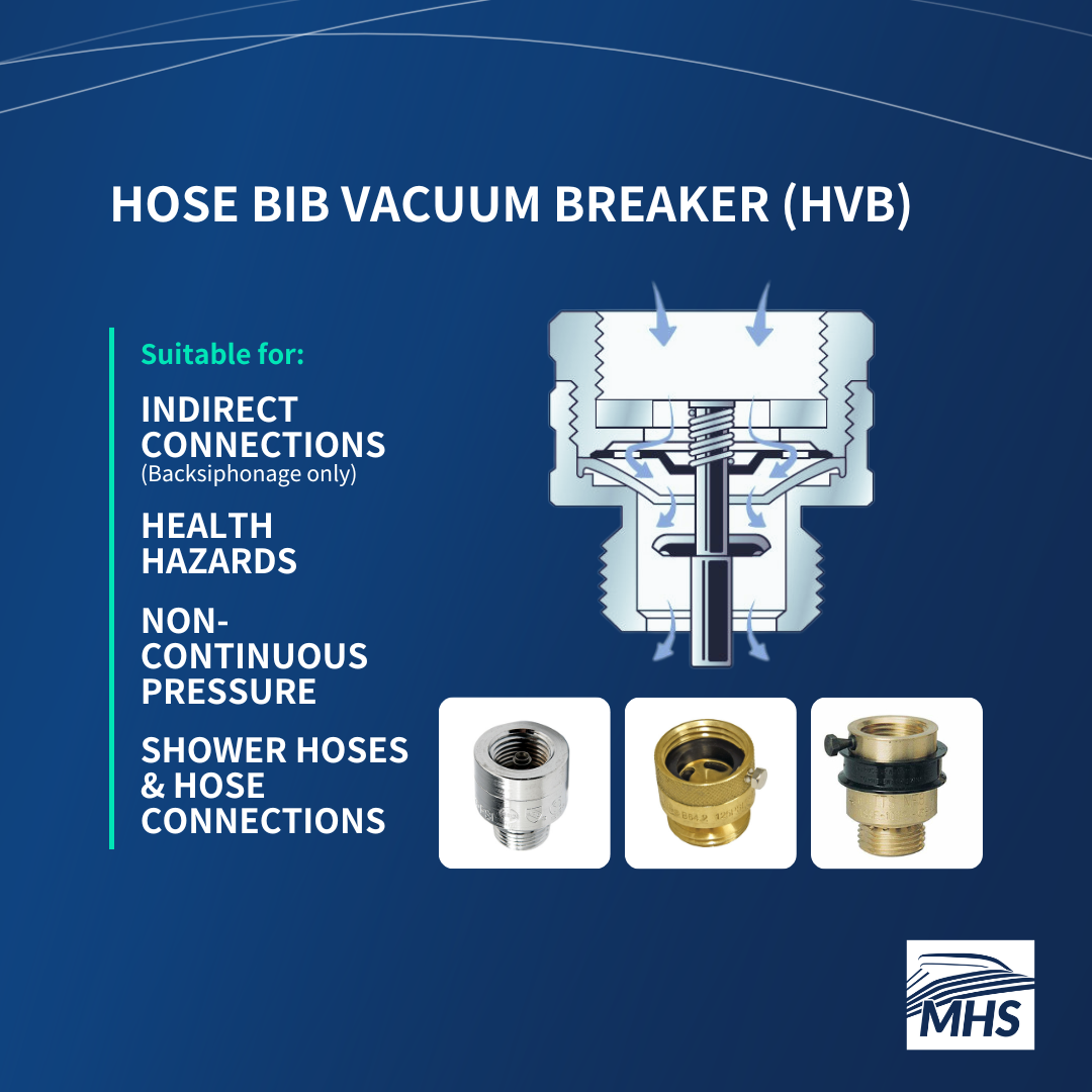
A Hose Bib Vacuum Breaker (HVB) is a simple device that attaches directly to the hose bib threads, which are the spiral grooves around the faucet opening. Think of it like screwing a lid onto a jar; the threads align, allowing you to twist it on securely. Some HVBs also feature a set screw to prevent loosening and ensure the HVB cannot be easily removed.
Once installed, turn on the water and check for any leaks around the connection. If you notice any leaks, tighten the HVB further. HVBs must be installed vertically, with the inlet and outlet ports on opposite sides, and positioned at least six inches above the deck.
Usage Guidelines
Similar to atmospheric vacuum breakers, HVBs are specifically designed to prevent backsiphonage. They are not suitable for continuous pressure but can protect against health hazards, as hoses can connect to various sources and easily become contamination points. For instance, a hose connected to a faucet in a cabin bathroom and used to fill a private whirlpool spa bath—a shortcut sometimes used by crew—could introduce harmful substances into the potable water system if backflow occurs.
Despite their small size and low cost, these devices are extremely important because hoses are typically the most common unprotected cross-connection. HVBs are also likely to be fitted to all hand-held showers on board. Unless the shower hose can be permanently restrained or shortened to achieve an appropriate air gap between the showerhead and the spillover level from the bath or shower tray, an HVB needs to be installed.
How Does an HVB Work?
HVBs feature a spring-loaded check valve that opens when water supply pressure flows through the valve, allowing water to pass through the hose and out the nozzle. When the water is turned off, or if the water flow reverses, the valve closes and seals the opening, simultaneously opening a vent to the atmosphere to prevent contaminants from entering the water supply.
Dual Check Valve Assembly with Atmospheric Vent
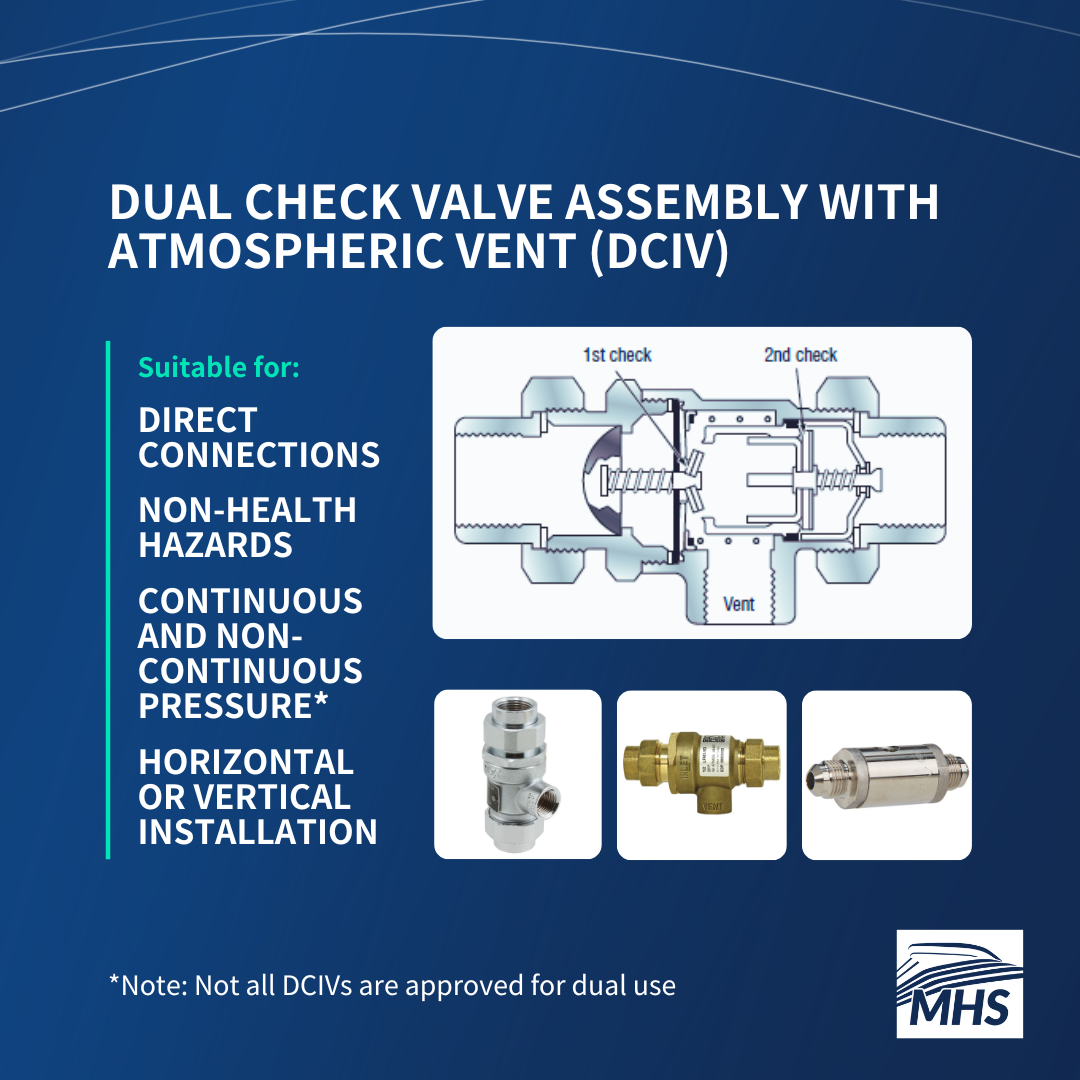
A Dual Check Valve Assembly With Atmospheric Vent (DCIV) consists of:
- Two Independent Spring-Loaded Check Valves: These valves ensure water flows in only one direction, preventing backflow. The redundancy provided by having two check valves means that if one fails, the other can still function, enhancing safety.
- An Atmospheric Vent: Located in an intermediate chamber between the two check valves, this vent offers an additional layer of protection against backflow.
DCIVs are designed to handle direct connections that are subject to backpressure and backsiphonage. They are suitable for both continuous and non-continuous pressure applications, although not all DCIVs are approved for dual use. Generally, these devices are intended for non-health hazard cross-connections, where the risk of contamination is low.
Applications on a Cruise Ship
On board, DCIVs are used in various applications to ensure water safety:
- Boiler Feed Lines (e.g., Watts 9D)
- Ice Machines (e.g., Watts LF9D)
- Hair Salon Sinks (e.g., Watts LFN9)
Additionally, some DCIVs, like the Watts SD-3, are specifically designed for carbonated beverage dispensers typically found in restaurants and bars. When carbon dioxide mixes with water to create carbonated water, it forms carbonic acid. If this acid flows back into copper piping, it can leach copper from the pipes, leading to copper poisoning.
Testable Backflow Prevention Devices
Testable BFPs are generally larger and more expensive but offer the advantage of functionality testing, providing greater confidence in their ability to prevent backflow and contamination.
On a cruise ship, these devices are almost exclusively used for cross-connections where the risk of contamination is higher (i.e., health hazards). VSP requires these devices to be tested upon installation, after repairs, and at least once a year to ensure they are operating as intended.
Examples include:
Pressure Vacuum Breaker Assembly
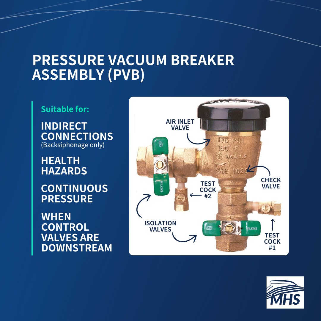
The Pressure Vacuum Breaker Assembly (PVB) is a step up from the basic atmospheric vacuum breaker. Designed to handle continuous pressure, a PVB is perfect for applications where downstream shut-off valves are in place. Think of these shut-off valves as light switches—they can completely stop or allow water flow, which is essential for maintenance or emergencies. Imagine having to shut off water to an entire galley just to fix one piece of equipment.
How a PVB Works
A PVB consists of several key components:
- Valve Body: This houses a spring-loaded check valve and an air inlet valve. If the water pressure drops (like from a burst pipe or sudden demand in supply), the check valve closes to prevent backflow. Simultaneously, the air inlet valve opens, letting air into the system. This breaks the vacuum and stops contaminated water from being siphoned back into the potable water supply.
- Isolation Valves: Found on both the inlet and outlet sides of the PVB, these valves allow you to stop the water and isolate the device from the rest of the system, making it easier to perform repairs or replacements.
- Test Cock 1: Located upstream of the check valve, this test cock allows for testing the pressure and functionality of the check valve.
- Test Cock 2: Positioned downstream of the check valve and before the air inlet valve, this is used to test the air inlet valve and ensure it opens correctly when the pressure drops.
Unlike AVBs, the spring-loaded check valves in a PVB allow the device to function under continuous pressure. The springs in these valves prevent them from getting stuck, even when pressure is applied for extended periods.
PVBs must be installed at least 12 inches above the highest point of use or piping downstream of the assembly, and they need to be upright with the air inlet valve on top. This orientation is crucial for the device to function correctly.
Limitations & Considerations
While PVB assemblies are effective, they do have some limitations. They are only suitable for indirect connections, offering protection exclusively against backsiphonage. Nevertheless, they are valuable in controlling health hazards and can be used for cross-connections to HVAC systems, laundry equipment, and recreational water facilities (RWFs).
One downside is that PVBs can occasionally discharge water, which can be problematic in indoor areas and create other public health issues, such as providing conditions that attract pests. To address this issue, we turn to the Spill Resistant Pressure Vacuum Breaker Assembly, which is designed to manage water spillage more effectively.
Spill Resistant Pressure Vacuum Breaker Assembly
A Spill Resistant Pressure Vacuum Breaker Assembly (SVB) represents an advanced version of the PVB. This assembly was developed to address the issue of water spillage associated with PVBs, making it suitable for areas on board where the occasional water discharge from a standard pressure vacuum breaker is undesirable.
When an SVB is in a backsiphonage state, it operates similarly to a pressure vacuum breaker. However, the key difference is that an SVB includes a spill-resistant mechanism that seals the air inlet valve during startup, before the check valve opens. In a PVB, the check valve and air inlet operate independently of each other; this is not the case with an SVB.
Unlike a pressure vacuum breaker, the water in an SVB does not need to travel past the check valve to close the air inlet valve. This design significantly reduces the water spillage typically seen with a PVB. The SVB offers the same level of protection as a PVB and is restricted to the same applications.
Reduced Pressure Backflow Assembly

When considering protection against health hazard backpressure and backsiphonage, our options are limited to either an air gap or a Reduced Pressure Backflow Assembly (RPBA).
How Does an RPBA Work?
An RPBA, also known as an RP Assembly, operates on the principle that water will not flow from a lower pressure zone to a higher pressure zone.
Here’s a simplified breakdown of how it works:
- Check Valves: The RPBA has two spring-loaded check valves. The first check valve reduces the supply pressure. If it fails, the second check valve acts as a backup to prevent backflow.
- Differential Relief Valve: Positioned below the first check valve, this valve monitors the pressure between the two check valves. Under normal conditions, it stays closed. If the first check valve leaks, the pressure increases, causing the relief valve to open and discharge water.
- Backflow Event: If either check valve leaks, the relief valve ensures that the pressure in the zone between the two check valves remains lower than the supply pressure by discharging water to the atmosphere. This prevents contaminated water from flowing back into the potable water supply. However, this mechanism is also why potable water lines downstream of RP Assemblies are not marked as potable, as the device may have been contaminated by the water discharged through the relief valve.
The RPBA unit also includes two shutoff valves (one upstream and one downstream of the check valves) and test cocks for field testing.
Applications on a Cruise Ship
Reduced pressure assemblies are suitable for continuous pressure applications and can be installed horizontally or vertically, depending on the model. They should be installed at least twelve inches above deck level or the finished surface of the surrounding area. This elevation supports with gravity drainage and access for maintenance and inspection. One downside of an RPBA is that it will occasionally discharge water. In a catastrophic event, it can discharge a significant amount, potentially causing flooding.
They are used for cross-connections that pose a significant health hazard to the potable water supply and may be found in areas such as:
- International Fire Shore Connections: Located in the potable water bunker stations
- Hi-Fog Systems: Used for fire suppression
- Water Softener And Mineralizer Drain Lines
- Reverse Osmosis Units & Evaporators
- Gray Water Systems: Wastewater from galley equipment, drains, showers, sinks, handwash basins, etc.
- Washing Machines (like those in the Main Laundry)
- Technical Water Systems
- RWF Machinery Rooms
Many of these applications operate at higher pressures due to the presence of pumps and other components. This increased pressure can create a risk of backpressure, where water could potentially flow back into the potable water supply if not properly controlled.
Conclusion
The hazards posed by inadequately protected cross-connections on cruise ships represent significant risks to the health and safety of both passengers and crew. These dangers extend beyond backflow events. Cross-connections between potable and non-potable water systems can introduce Legionella and other opportunistic bacteria into the drinking water supply. The likelihood of Legionnaires’ disease increases with inadequate backflow protection and potential ingress from cross-connections, particularly during maintenance activities. Additionally, inappropriate materials in the potable water supply can provide nutrients for Legionella growth and biofilm formation, further exacerbating the problem.
Although the complexities of potable water systems and backflow prevention can be challenging, it is essential for cruise companies to ensure that due attention is given to their cross-connection control programs. The seemingly innocuous liquid coursing through a ship’s pipes can pose significant health risks, especially in terms of infectious disease transmission.
The safety of the potable water supply is as vital as any other aspect of cruise ship operations. Ensuring robust cross-connection control is not just a regulatory requirement but a commitment to the well-being of everyone on board.